
This year at BlackHat USA I talked about the methodology we developed to audit encrypted USB keys and some of the attacks we found while applying it. This is a joint work with Elie, Rémi, and Sven. You can get the slides here or watch the talk on Youtube.
As Alex Drozhzhin from Kaspersky wrote a very good summary of our talk I’m not going to do another one here. Instead this post focuses on some of the technical details that we didn’t had a chance to cover during the talk. In particular I will explain how we removed the epoxy coating, and how did we de-soldered and then re-balled the BGA.
Disclaimer: I’m not claiming that the methods offered in this post are the only way to do what we did nor that it is the best way to do it. However they worked well for us and if you were to do the same, they are a great starting point that can save you a lot of time. A key advantage of the methods we used is that they don’t require very expensive hardware. hey do however require quite a bit of practice though!
If you have suggestions about improving any of the tips I’m giving here, don’t hesitate to leave a comment below.
Dealing with epoxy
Secure keys use component epoxy coating to slow down reverse engineering effort as epoxy make it harder to access the key internal components.
During our audit we discovered that some manufacturers were using low grade quality epoxy coating, which is dissolvable in acetone. For example this was the case for the model visible in the picture below:

Key with dissolvable epoxy coating
Testing for improper epoxy is obviously the first thing to do as it is super easy: simply put some acetone on a piece of rag and rub the coating with it. Should the rag becomes black it is cheap epoxy! If that is the case, all you need to do to remove epoxy is to put the USB sticks in a bath of acetone during at least 10 hours. I used a shooter glass to avoid wasting too much acetone and ensure that the USB key could stay almost vertical. Keeping the key vertical ensures that the dissolved epoxy will drop on the bottom of the glass. After removing the key from the acetone bath simply clean the remaining resin with acetone, a clean wipe, and an ESD safe brush. You should end-up with a key that looks like this at the end of the process:

USB key once epoxy has been removed with acetone
If the epoxy coating is not dissolved by acetone, it’s still possible to remove it but it requires more patience. I used a combination of a hot air gun to soften the epoxy coating and a precision knife to scrape, piece by piece, the coating. The trick here is to find the sweet spot for the temperature:
- Too low and it will have close to no effect and it will take you ages to remove the coating.
- Too high and the solder will start melting, potentially making short circuits below the coating, the compound used on the packages of the components will also be softer and you may accidentally scrape it, revealing the internal die and breaking the bonding wires.
Empirically I found 285 degrees Celsius to be optimal for the keys I had to deal with: it softens the resin enough to allow you to scrape it while keeping the solder joints solid (lead-free solder has a higher melting point) and without softening the resin protecting the chips. Then patience is the key: scrape the epoxy gently without using strength or you will damage something. To hold the PCB while handling the hot air gun in one hand the precision knife on the other hand, I used my reliable PCBite. They are made of metal so they won’t be damaged in the process and they will hold the key firmly enough. At the end of the process I either let them cool down before removing the PCB or I used gloves to avoid burning my fingers.
Another trap on this process is to heat the USB key in a non uniform way. I found it particularly difficult on the models with a PIN pad because the sticker with the tactile domes creates some tension on the PCB and the first key I tried to clean was broken at the end because the PCB bent and some internal copper traces broke.
As a workaround, I paid extra attention to heat progressively the PCB and from time to time reheat the whole PCB and not only the spot I wanted to work on.
Desoldering the memory chip
Once the coating has been removed or if there was no coating at all, you may want to remove the memory chip, should it be a BGA or a TSOP. If the key was dipped into epoxy, it will require extra care because some of the compound will sit between the chip and the PCB, acting like glue. Lifting the chip with strength will damage either the PCB or the chip if not both.
Desoldering a chip always starts the same way:
If the PCB has components on both sides, secure the parts you don’t want to remove by using Kapton® tape
Put some soldering flux on the component you want to desolder; it will help the solder joints to melt quicker and it will also soften the leftovers of the epoxy
Preheat the PCB with the hot air gun in order to avoid bending it
Heat the component and the surrounding area (keep moving the nozzle to avoid damaging anything with too much heat) until you see the solder melting
If there was some epoxy, use the finest blade you can have on a precision knife and slide it very gently between the PCB and the component. This is very tricky to do because you don’t want to damage the pads of a BGA nor the copper traces of the PCB with the tip of the blade.
Poke gently from time to time with a pair of tweezers to see if the component moves and lift it with the tweezers as soon as the component seems to move freely
As you can see in the following picture, even if I was super careful, many pads (fortunately, most of them were not used) were torn away from the PCB and you can see the epoxy that went down the BGA chip, gluing it to the PCB.

Epoxy that went down the BGA and some (unused) pads were snatched away
Reballing a BGA chip
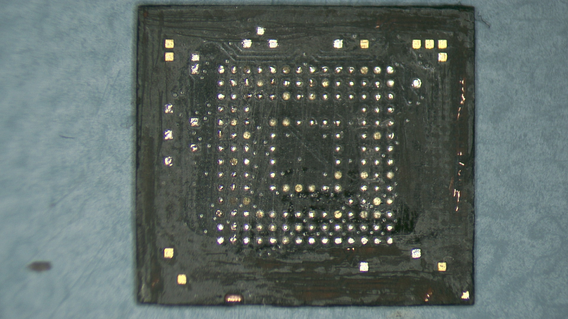
The first step before actually reballing the chip is to clean it: you may have some epoxy on it, some snatched away pads from the PCB, or in any case some solder on it like on the following picture.

Desoldered BGA chip that need to be cleaned then reballed
For a TSOP package, I simply used a precision knife with a sharp blade and go between the pins to remove the epoxy. Depending on how well it works, I either clamp the chip with PCBite to be able to heat the chip while scratching it or I simply hold the chip with a pair of tweezers.
But BGA chips are not as easy to deal with. For them I couldn’t come up with a magical procedure so I clamped the chip with my PCBite, I put some soldering flux on the chip and using a chisel tip on my soldering iron set at a high temperature, I started scratching the BGA chip. When the flux became too brownish, I cleaned everything with isopropyl alcohol and started again the procedure. To remove the excess of the solder, I simply used a desoldering wick. I also used my precision knife to reshape the BGA, removing the epoxy compound around the chip (otherwise it wouldn’t fit in the BGA socket). After at least one hour, I ended up with a relatively cleaned chip as you can see on the picture below. Not perfect but the chip was flat enough and the pads were all cleared from epoxy residue.
Cleaned BGA
Normally reballing a BGA chip requires a special kit with a clamp, a stencil and some solder balls. I recently find a cheap kit that contains everything on Multi-Com and I’m probably going to add that to my lab soon. But the first BGA, I did it only with a soldering iron! Note that I won’t recommend doing it as it’s much more complicated and the result is not as reliable as with the stencil and the solder balls.
But for my curious readers, I covered the chip with solder flux, I used a spoon tip on my iron that I filled with solder and I started rubbing the chip. Once I was satisfied enough with the result, I cleaned everything with isopropyl alcohol. As crazy as it may seem, it worked pretty well for me and the balls were even enough (or the ZIF socket was tolerant enough) to make good contacts. Here is the picture after reballing:

Manually reballed BGA
Conclusion
I really enjoyed working on that project, especially making it accessible to everyone by keeping the tools and techniques on a budget. The results are not as perfect as with the proper tools but it forced me in being a bit more inventive. As an example we also thought about creating our own PCB to replace the BGA chip but it turned out that not only the PCB was quite expensive due to the precision for the pads but it was not as easy as it may seem to solder such PCB on another PCB!

Our attempt at a custom PCB to replace an eMMC BGA chip
I hope that the details published on this article and at our talk will help people auditing their keys and that the results will be shared across the community to help decision makers and individuals to keep their data secure.
If you are interested in watching our presentation and discover the security flaws we uncovered on some models, here is the video that BlackHat recently released on Youtube.